Introduction: Use switch sensors and four-way digital tubes to complete the countdown function.
Advanced: Positive timing, timed at specified time intervals.
Advanced: Currently unavailable
Experiment: Currently unavailable
1、Teaching objectives (knowledge preparation)
Know four digital sensors.
Four way digital nixie tube can be controlled by programming.
Be able to apply project equipment in combination with life application scenarios.
2、Teaching tasks
Complete the countdown programming by using the switch sensor and four-way digital nixie tube, and the countdown number is displayed on the four-way digital nixie tube.
3、Preparation of teaching environment and equipment
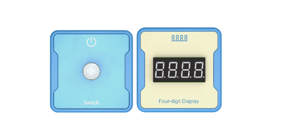
Equipment List: Image (with label number 123456)
Equipment Serial Number Table
| Serial number | number | equipment | Specifications | quantity |
| 1 | Switch | 1 | ||
| 2 | Four digit digital tube | 1 | ||
| 1 |
Software: Smart Code programming software.
Hardware: SMART Code kit: Switch, four digit digital tube.
Other: Several building block devices.
Detailed List of Structural Components
| Serial number | number | equipment | Specifications | quantity |
| 1 | 3-hole beam | 18 | ||
| 2 | 7-hole beam | 6 | ||
| 3 | 13-hole beam | 6 | ||
| 4 | T-shaped beam | 6 | ||
| 5 | Black sales | 54 |
Note: Materials required to fix a set of sensors: 6 3-hole beams, 2 7-hole beams, 2 13 hole beams, 2 T-shaped beams, and 18 black pins.
4、Project Practice Process
(Summary of Knowledge Points: 1. Components. 2. Program Modules. 3. Program Design)
1、Project video (in video format)
2、Project Steps
1.According to the list of items, fix the switch and four digit clock digital tube.
2.Use smart code programming software to complete the programming design. Countdown statement encapsulation.
3.Use smart code software for programming.
First, complete the switch logic settings and use the advanced functions of the switch sensor. The example code is as follows:
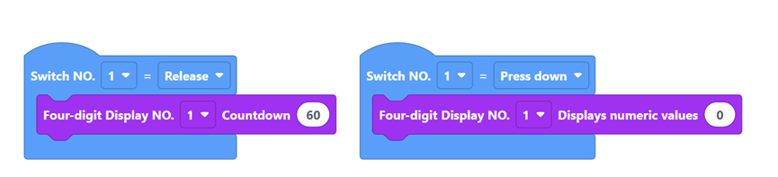
Then, reset the number on the four-way digital nixie tube. When the switch sensor is pressed, the four-way digital nixie tube displays “0000”, and the example code is as follows:
Then, release the switch sensor and start the countdown. The example code is as follows:
Finally, complete all the codes. The example code is as follows:
4.Run the program, debug the switch and use the timing function.
5.Optimization and improvement plan.
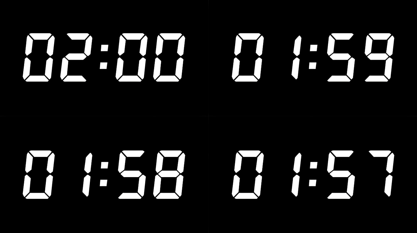
6.Interesting thinking: whether the comparison between the program countdown and the clock countdown is accurate. Reverse the value of the rotary potentiometer.
3、Reflection and discussion:
Experimental results
Data records: Table 1 and Table 2
Experimental conclusion:
5、Extension and Expansion
Reflection and exploration:
Question 1:
Question 2:


