Getting started: use the switch sensor and actuator to open and close the electric door. Display the working state of the electric door in combination with RGB light.
Advanced: None
High level: None
Experiment: None
1.Teaching objectives (knowledge preparation)
Know the steering gear and its types and parameters.
It can control the steering gear through programming, and can display different working states in combination with RGB lights.
Be able to apply project equipment in combination with life application scenarios.
2.Teaching tasks
Switch sensor and actuator are used to open and close the electric door. Display the working state of electric door with RGB light.
3.Preparation of teaching environment and equipment
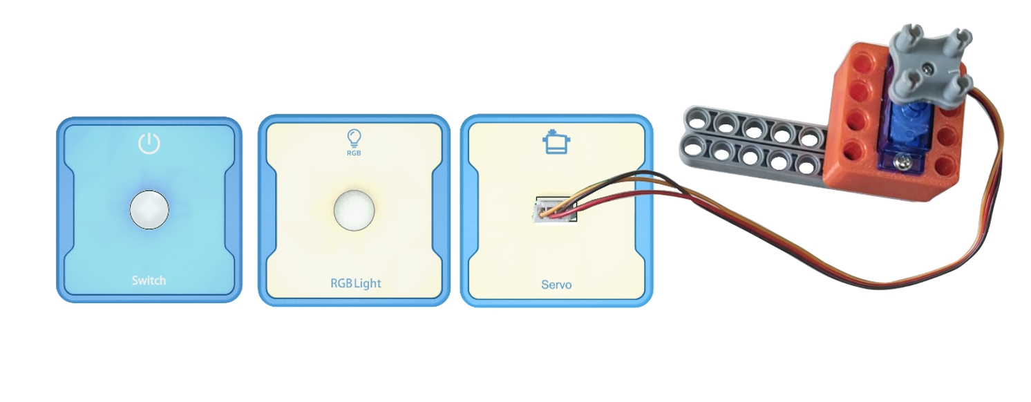
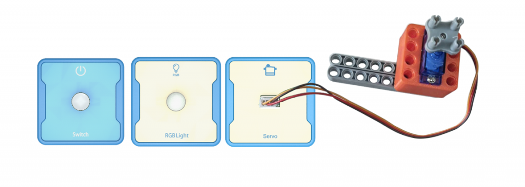
Equipment List: Image (with label number 123456)
Equipment Serial Number Table
| Serial number | number | equipment | Specifications | quantity |
| 1 | Switch | 1 | ||
| 2 | Servo | 1 | ||
| 3 | RGB Light | 1 | ||
Software: Smart Code programming software.
Hardware: SMART Code kit: Switch, Servo, RGB Light.
Other: Several building block devices.
Detailed List of Structural Components
| Serial number | number | equipment | Specifications | quantity |
| 1 | 3-hole beam | 18 | ||
| 2 | 7-hole beam | 6 | ||
| 3 | 13-hole beam | 6 | ||
| 4 | T-shaped beam | 6 | ||
| 5 | Black sales | 54 |
Note: Materials required to fix a set of sensors: 6 3-hole beams, 2 7-hole beams, 2 13 hole beams, 2 T-shaped beams, and 18 black pins.
4.Project Practice Process
(Summary of Knowledge Points: 1. Components. 2. Program Modules. 3. Program Design)
1.Project video (in video format)
2.Project Steps
1.Fix the switch sensor, steering gear and RGB light according to the list of items.
2.Use the steering gear to build the opening and closing door.
3.Use smart code programming software to complete the programming design.
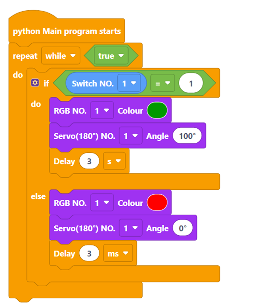
First, complete the switch logic setting. The example code is as follows:
Then, adjust the steering gear rotation angle to determine the steering gear angle when opening and closing the door. The sample code is as follows:
Then, in combination with RGB lights, the green light is on when opening the door and the red light is on when closing the door. The example code is as follows:
Then, combined with RGB lights and actuator control statements, test the status of door opening and closing. The example code is as follows:
Finally, complete all the codes. The example code is as follows:
4.Run the program, debug the switch and use..
5.Optimization and improvement plan.
6.Interesting thinking: none at present.
3.Reflection and discussion:
Experimental results
Data records: Table 1 and Table 2
Experimental conclusion:
5.Extension and Expansion
Reflection and exploration:
Question 1:
Question 2:


