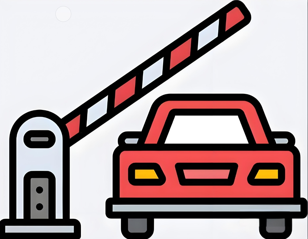
Getting started: use the infrared sensor to detect whether there is a car in front of the barrier, and then the steering gear controls the rise and fall of the barrier. RGB lights and dot matrix display the status of the barrier.
Advanced: image recognition, which can automatically record license plate information.
High level: None
Experiment: None
1.Teaching objectives (knowledge preparation)
Know the steering gear and its working principle and parameter range.
Through programming, the switch of the gate can be realized by using the infrared sensor and actuator, and the gate status can be displayed by combining the dot matrix screen and RGB light.
Be able to apply project equipment in combination with life application scenarios.
2.Teaching tasks
An automatic lane gate device is designed by using infrared sensor, steering gear, dot matrix screen and RGB lamp.
3.Preparation of teaching environment and equipment
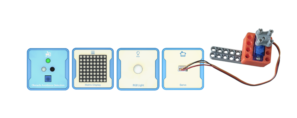
Equipment List: Image (with label number 123456)
Equipment Serial Number Table
| Serial number | number | equipment | Specifications | quantity |
| 1 | Obstacle Avoidance Detection | 1 | ||
| 2 | Servo | 1 | ||
| 3 | Matrix Display Dot matrix LED | 1 | ||
| 4 | RGB Light | 1 | ||
Software: Smart Code programming software.
Hardware: SMART Code kit: Obstacle Avoidance Detection, Servo, Matrix Display Dot matrix LED, RGB Light.
Other: Several building block devices.
Detailed List of Structural Components
| Serial number | number | equipment | Specifications | quantity |
| 1 | 3-hole beam | 24 | ||
| 2 | 7-hole beam | 8 | ||
| 3 | 13-hole beam | 8 | ||
| 4 | T-shaped beam | 8 | ||
| 5 | Black sales | 72 |
Note: Materials required to fix a set of sensors: 6 3-hole beams, 2 7-hole beams, 2 13 hole beams, 2 T-shaped beams, and 18 black pins.
4.Project Practice Process
(Summary of Knowledge Points: 1. Components. 2. Program Modules. 3. Program Design)
1.Project video (in video format)
2.Project Steps
1.Fix the infrared sensor, steering gear, dot matrix screen and RGB light according to the list of items.
2.The infrared sensor is aimed at the front of the gate, and the steering gear controls the lift of the gate. In the normal state, the RGB red light is always on, and the dot matrix display shows no traffic. When a car comes in, the dot matrix display shows the passable status, and the RGB green light is always on.
3.Use smart code programming software to complete the programming design.
First, complete the switch logic setting. The example code is as follows:
Then, the infrared sensor is debugged to clarify the test range. The sample code is as follows:
Then, the steering gear rotation angle is tested to realize the gate lifting. The sample code is as follows:
Then, debug the dot matrix screen and RGB lighting effect. The example code is as follows:
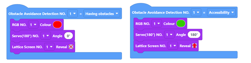
Then, combined with the detection value of the infrared sensor, when a vehicle arrives, the steering gear control gate rises, the dot matrix screen displays the passable state, and the green light of RGB is always on. Otherwise, the steering gear control gate drops, the dot matrix screen displays no passage, and the red light of RGB is always on. The sample code is as follows:
Finally, complete all the codes. The example code is as follows:
4.Optimization and improvement plan.
5.Interesting thinking: none at present.
3.Reflection and discussion:
Experimental results
Data records: Table 1 and Table 2
Experimental conclusion:
5.Extension and Expansion
Reflection and exploration:
Question 1:
Question 2:


