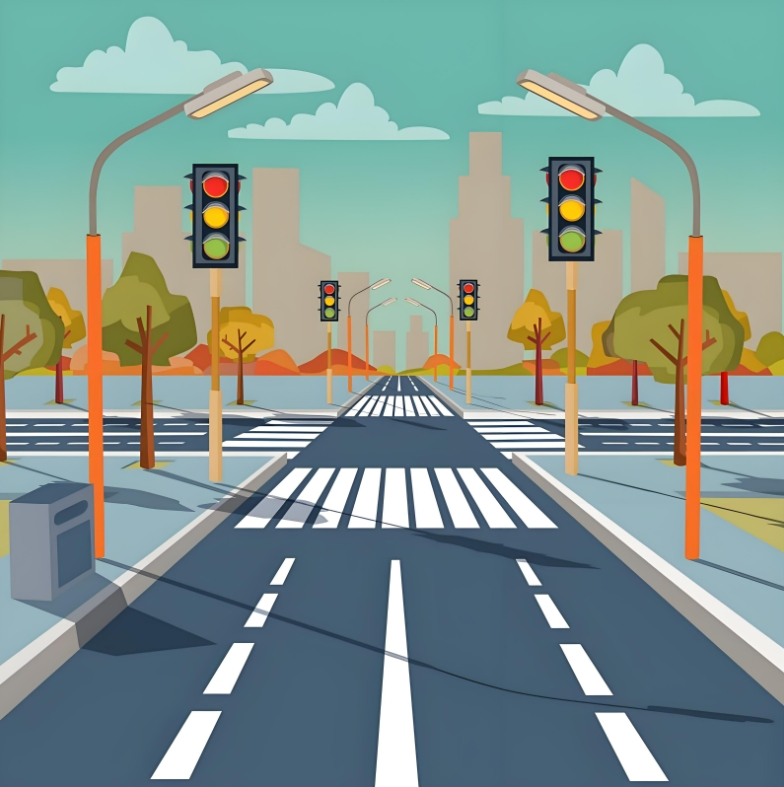
Introduction: switch sensor, four-way digital tube, traffic lights.
Advanced: None
High level: None
Experiment: physical experiment: three primary colors of light.
1.Teaching objectives (knowledge preparation)
Know the logic of traffic lights and RGB lights.
Traffic lights can be controlled by programming.
Be able to apply project equipment in combination with life application scenarios.
2.Teaching tasks
The switch sensor and traffic lights are used to complete the lighting logic of various lights, and the traffic light logic is completed in combination with the countdown.
3.Preparation of teaching environment and equipment
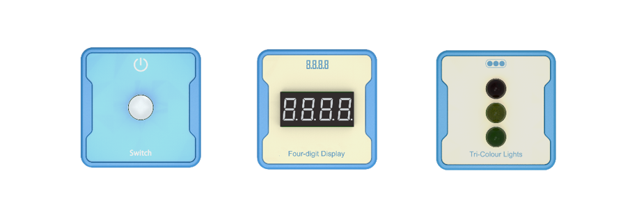
Equipment List: Image (with label number 123456)
Equipment Serial Number Table
| Serial number | number | equipment | Specifications | quantity |
| 1 | Switch | 1 | ||
| 2 | Four digit digital tube | 1 | ||
| 3 | Tri-Colour Lights | 1 |
Software: Smart Code programming software.
Hardware: SMART Code kit: Switch, four digit digital tube, Tri-Colour Lights.
Other: Several building block devices.
Detailed List of Structural Components
| Serial number | number | equipment | Specifications | quantity |
| 1 | 3-hole beam | 18 | ||
| 2 | 7-hole beam | 6 | ||
| 3 | 13-hole beam | 6 | ||
| 4 | T-shaped beam | 6 | ||
| 5 | Black sales | 54 |
Note: Materials required to fix a set of sensors: 6 3-hole beams, 2 7-hole beams, 2 13 hole beams, 2 T-shaped beams, and 18 black pins.
4.Project Practice Process
(Summary of Knowledge Points: 1. Components. 2. Program Modules. 3. Program Design)
1.Project video (in video format)
2.Project Steps
1.According to the list of items, fix the switch sensor, traffic lights and four digit clock nixie tube.
2.Use smart code programming software to complete the programming design. Countdown statement encapsulation.
3.Use smart code software for programming.
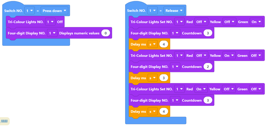
First, complete the switch logic setting. The example code is as follows:
Then, when the switch button is pressed, the traffic lights go out, and the countdown displays 0. The example code is as follows:
Then, when the switch button is released, the light will be green for 4 seconds, yellow for 3 seconds and red for 4 seconds. The example code is as follows:
Finally, complete all the codes. The example code is as follows:
4.Run the program, debug the switch and use the timing function.
5.Optimization and improvement plan.
6.Interesting thinking: whether the comparison between the program countdown and the clock countdown is accurate.
3.Reflection and discussion:
Experimental results
Data records: Table 1 and Table 2
Experimental conclusion:
5.Extension and Expansion
Reflection and exploration:
Question 1:
Question 2:


